
I am wiring this up, and I would like to limit the current being drawn from 18v DC/DC converter.
What would be the simplest way of doing this?
I am wiring this up, and I would like to limit the current being drawn from 18v DC/DC converter.
What would be the simplest way of doing this?
A current shunt is a resistor that can handle the full current of the motor. You would probably want a 0.1Ω resistor rated for at least 1 watt.
You measure the voltage drop across it to determine the current. The voltage will be quite low. With a 0.1Ω resistor and a 2A load, it will be 0.2V. You want to amplify that up closer to the full scale input of the ADC to get a decent resolution. An op amp with a gain of 10 would work well for that. Use a rail to rail op amp that can run from the 3.3V power supply.
Here is a schematic:
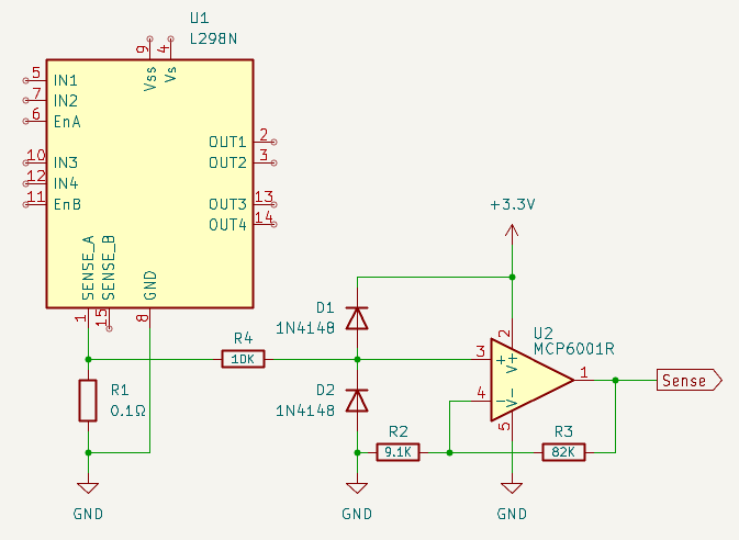
R4, D1 & D2 protect the op amp input from any spikes the motor produces.
Oh, wow!
Very nice! Thank you so much for doing this!
Is it correctly understood that the “Sense” line can be hooked up directly to the ADC input on the Pico?
Now, just because I am quite ignorant when it comes to all this, I will venture to ask: This is better because it is closer/faster/more exact than using the Hall current sensor, or? With my complete lack of understanding, I had the impression, that I could more or less “just” connect the sensor to the “right spots” and directly to the ADC input on the Pico, and my work in the Pico would be similar to this setup?
Don’t get me wrong - I can see this is much more elegant - and won’t be bothered by whatever else might use power on the same rail. But since it might be simpler for me to use a more “out of the box” component like the sensor, instead of my bad soldering of several discrete components… Also however ridiculous it might seem it is much easier for me to source 5 modules - than 5 of each of these components (I would have to buy many of each, and waste most).
So I have to ask. :-)
The sense output from the op amp connects directly to an ADC input. The output is 1 volt per amp. If sense_a is already connected to ground, you will have to disconnect it.
The hall effect current sensor will work fine too. They do tend to have an offset, but you can calibrate that out in software. Just take a reading when the motor is off and subtract it from the reading when the motor is on. If you do use the hall effect sensor, you could connect it between sense_a and ground so it will only measure the motor current.
Thanks again!
Does this look OK, to your trained eye then?
Yes, that is wired correctly.
Did you get the 5 amp current sensor or the 30? The higher current ones output less voltage per amp, which will make it harder to measure small currents.
I got the 30 amp. My thought was that the motor uses up to around 20 watts when running so a little more than 1 amp, and as far as I can tell, it tries to pull around 6-10 amps(!) when stalled/almost stalled. I think this should mean a fairly large spike, that I should be able to detect even with the 30A device.
But of course it is probably just absurd overkill, and will make my life more complicated. Fortunately they are absurdly cheap and easy to buy, so if the resolution turns out to be a problem, I can get another range, when I have some empirical data. The other ranges should plug in, in the same place right?
The other ranges connect exactly the same.
Sorry I forgot to ask: I should cut the SENSE-A connection to ground right?