
I am wiring this up, and I would like to limit the current being drawn from 18v DC/DC converter.
What would be the simplest way of doing this?
You must log in or register to comment.
I don’t think there’s a good way to adapt this circuit to provide current limiting on the 18v rail. Supposing that it was possible, what behavior do you want to happen when reaching the current limit? Should the motor reduce its output torque when at the limit? Should the 18v rail completely shut down? Should the microcontroller be notified of the current limit so that software can deal with it? Would a simple fuse be sufficient?
All of these are possible options, but with various tradeoffs. But depending on your application, I would think the easiest design is to build sufficient capacity on the 18v rail so that the motor and 5v converter inherently never draw more current than can be provided.
Thanks for taking time to look at this! :)
The issue is that if something is blocking the motor, or the limit sensor is not working, the motor should stop before burning itself out or breaking stuff.
I did buy a hall effect current sensor (https://www.aliexpress.com/item/1005006222090940.html) that I was thinking of connecting to the pi pico on an interrupt enabled pin, so I could cut off the engine output at the source, and alert my upstream controller. But I just couldn’t wrap my head around how to implement it.
Another option that I considered was putting some kind of fuse on the 18v rail and try to figure out how to detect if the 18v rail was dead and feed that to the pico - but then I’m not really sure how much simpler (if at all) that would be.
The picos inputs are 3.3v btw.
In that case, I would suggest looking at a different motor driver. The driver you’ve specified doesn’t seem to have any provisions to detect a motor stall, which is something that other drivers can potentially do. Ideally, the driver would detect the back EMF from the stall and inform the microcontroller, which would then decide to stop movement.
An external current sensor might work, but that’s adding to the part count and might not be as capable as built-in functionality within the motor driver. Plus, fancier motor drivers have some neat features that you could take advantage of as well. I think it would be more prudent to consider a different driver before adding additional parts.
The L298 has two sense pins. Connect a current shunt between each sense pin and ground and you can measure the motor current. Use an op amp to amplify it and measure it with the ADC in the microcontroller. The microcontroller can stop the motor if the current gets too high.
Ah, I entirely missed the sense pin when skimming the datasheet.
That said, using a shunt for an inductive load like a motor may have to contend with the corresponding spikes caused when switching the motor. This just means the thing doing the sensing needs to tolerate the spikes. Or mitigate them, with either a snubber or a flyback diode (is this actually doable with an H bridge?).
As for the op-amp and ADC, if we already accept the additional of the op-amp part, it is also feasible to instead use a comparator with a reference voltage set for the max safe current. The digital output of the comparator can then be fed directly to the microcontroller as an interrupt, providing fast reaction without the sampling time of an ADC. But this would be so quick that the spikes from earlier could get picked up, unless mitigated. It also means software will not know the exact current level, other than that it’s higher than the threshold set by the reference voltage.
Still, these solutions are adding to the part count. If that’s a concern, then I’d look for a motor driver with this functionality built in.
OK… I understand very little of this :( I am a software person. But could this comparison not be done with some hysteresis? The part count is not important as long as the parts aren’t terribly expensive, since this is exclusively for my personal use.
But could this comparison not be done with some hysteresis?
It can, but analog design is also not my forte.
The part count is not important as long as the parts aren’t terribly expensive, since this is exclusively for my personal use
In that case, the original suggestion of using an ADC and an op-amp would be the most flexible for software. You would, however, need to do some research on wiring an op-amp to amplify the sense voltage to something your microcontroller’s ADC is capable of resolving.
That sounds very cool - and way beyond my own understanding :-)
Is this something you could actually help with sketching out for me?
I found the datasheet for the L298 and I can see that for my use (I am using just out 1 and out 2) it should be pin 1 (Sense A) that should be relevant, right?
This looks like it is connected to gnd on the driver board (I can easily cut this connection).
Unfortunately I don’t understand what a current shunt is? :-)
It has me slightly worried that it says that pin 1 can go to -1v which I think would break the ADC input?
As far as I can tell the ADC input on the PICO accepts from 0 - 3.3v right?
Thanks a bunch for looking at this!
A current shunt is a resistor that can handle the full current of the motor. You would probably want a 0.1Ω resistor rated for at least 1 watt.
You measure the voltage drop across it to determine the current. The voltage will be quite low. With a 0.1Ω resistor and a 2A load, it will be 0.2V. You want to amplify that up closer to the full scale input of the ADC to get a decent resolution. An op amp with a gain of 10 would work well for that. Use a rail to rail op amp that can run from the 3.3V power supply.
Here is a schematic:
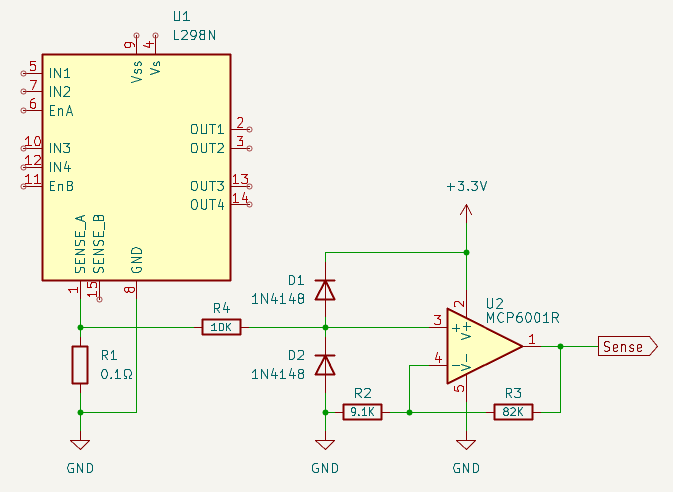
R4, D1 & D2 protect the op amp input from any spikes the motor produces.
Oh, wow!
Very nice! Thank you so much for doing this!
Is it correctly understood that the “Sense” line can be hooked up directly to the ADC input on the Pico?
Now, just because I am quite ignorant when it comes to all this, I will venture to ask: This is better because it is closer/faster/more exact than using the Hall current sensor, or? With my complete lack of understanding, I had the impression, that I could more or less “just” connect the sensor to the “right spots” and directly to the ADC input on the Pico, and my work in the Pico would be similar to this setup?
Don’t get me wrong - I can see this is much more elegant - and won’t be bothered by whatever else might use power on the same rail. But since it might be simpler for me to use a more “out of the box” component like the sensor, instead of my bad soldering of several discrete components… Also however ridiculous it might seem it is much easier for me to source 5 modules - than 5 of each of these components (I would have to buy many of each, and waste most).
So I have to ask. :-)
The sense output from the op amp connects directly to an ADC input. The output is 1 volt per amp. If sense_a is already connected to ground, you will have to disconnect it.
The hall effect current sensor will work fine too. They do tend to have an offset, but you can calibrate that out in software. Just take a reading when the motor is off and subtract it from the reading when the motor is on. If you do use the hall effect sensor, you could connect it between sense_a and ground so it will only measure the motor current.
Sorry I forgot to ask: I should cut the SENSE-A connection to ground right?
Ah… Since I am not a smart man, I have already invested too much (for the project) in several of these motor drivers. :-(
Out of curiosity, what is this project?
It is a networked window opener/closer for my house, all with parts sourced from China, since the commercially available openers are very overpriced IMHO. Which I guess also speaks a lot to the fact that I am a man with more time than money…
I like it!
I once endeavored to do something similar, but it would have been for opening the blinds in the morning and closing them after sunset.
Thanks. It has been fun, both doing the software, where I feel at home, but also the challenge of trying to do electronics, where I am completely lost :D You can’t imagine the amount of DC converters I have burnt out, or my absolute confusion why I couldn’t turn a motor on and off using a couple of relays! I must confess I still don’t understand, but at least now I know.
Turning a voltage sensing relay into a current sensing relay is basically just putting a small resistor in parallel with the sensing pins and setting the cutoff accordingly. Or like the other poster said, using the pico to do the same thing with pwm control, or just driving a FET on the power feed if you want to avoid writing pwm control code.
