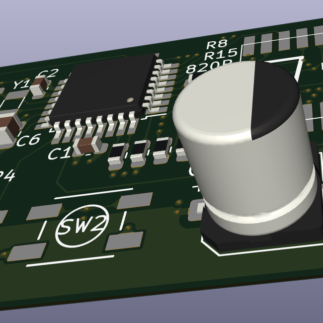
So i have these Rode Wireless Microphones at Work that you connect to your phone with a USB-C cable. Thing is the cable they ship with is absolute trash and breaks after about 3 uses. So i got the idea to try and build a 3d printed thingie with a protruding usb-c port that you could slide onto your phone sort of like the old iphone music docks. Then on the back you could slide in the rode receiver, thus eliminating any cable twisting. I thought this would be easiest if i had the pictured usb-c breakouts, because they have mounting holes that i could fix firmly into the 3d printed part. I picked a 24 pin version thinking this would cover all the necessary usb-c specs to get at least something like a usb 3.0 connection as I don’t think the rode mics need super high data transfer or power delivery above 5v. Alas the pictured “cable” didn’t do the trick and the mic wasn’t recognized by the phone. So I’m wondering would it even be possible to build something like this with breakouts or am I missing things. Do usb-c cables usually have chips that negotiate voltage and transfer specs between devices? Am i missing shielding, or is my wire gauge totally off?
I can probably still build a mic holder thingy using a short premade silicone cable, but I’m still curious if this setup could work in theory or if there are other breakouts that could make this work.
Thanks for your help!
No shielding - and like my electronics teacher used to say “you’re not soldering , you’re painting.” A lot less is needed. Heres another thing he used to say … “Solder does not make the connection… Solder makes a good connection permanent.” Cool guy. Anyway you’re on the right path - I bet you only need 4 wires . Due to shielding though just go buy a cable.
I need you to teach me to soldier. I’m terrible at it.
Confidence and flux. A lot of cheap solder skimps on the flux. It strips the corrosion of the contacts, and lets the solder flow smoothly. Rosin is also used for violin strings, and it’s the same stuff, but far cheaper than “proper” flux.
As for the confidence. When soldering, you apply heat and solder until it joins, or you back off completely. The worst thing to do is the tap tap tap method. The heat spreads to surrounding material and components, but is never concentrated enough to actually do the job.
Those 2 will get you VERY far. The other things to improve is hand position (brace your wrist on the work surface) and lighting. Office lighting is no good. You want as many lumens as you can, preferably daylight levels on the board. It lets your pupils close down, and increases your depth of vision.
Flux, you have a great point there. That you do paint with.
Squints
Some of your solder joins are a little close on that top connector.
If you’re wondering if USB C is really needed, buy a USB C to USB A adapter and try it out on a computer and see if it’s recognised.
If it works with USB A then you’ve only got four wires to
mess upsolder on your USB C boards.It’s a very short cable so you might get away with it, but don’t expect this to really work well. You need shielding around data pairs and they need to be twisted. All of the lengths need to be matched pretty closely as well. The soldering looks suboptimal, with too much solder added.
You are right that a lot of USB-C cables include chips to handle all sorts of things, but depending on the application this isn’t required.
I would just get a pre-made cable, they are cheap and available in all shapes and sizes. Breaking out data cables like this is pretty difficult (unless we are talking like 9600 baud RS-232/485). Modern data cables are like impossible engineering feats. It’s just because we use so many of them and we have machines to make a lot of them quickly, that they are as cheap as they are.
It looks like you may have some shorts.
But USB 3.0 is way more strict than 2.0. You essentially need twisted cables for the data line pairs at approximately the right impedance. It is way more finnicky to get working reliably.
You are likely getting massive amounts of crosstalk now with the cluster of untwisted cables going everywhere.
Try unsoldering the top side, using thinner cables to not get shorts, and looking up a pinout. Then twist all of the data pairs with each other and cleanly solder back on. The check for shorts between every neighboring pin.
It is possible that you might be better off only soldering the cables needed for USB2.0 as audio is very small bandwidth and most audio devices run on 2.0.
Also, solder them reverse from each other so the cable paths are straight so it is easier to see and wires don’t have to twist through each other.
Cables these days are super smart, there are micro controllers in modern cables that do alot of smart talking to the devices.
Would something like this solve your problem? If yes, it’s called something like “USB C U-turn adapter”. Search your favorite crapware platform for it :)
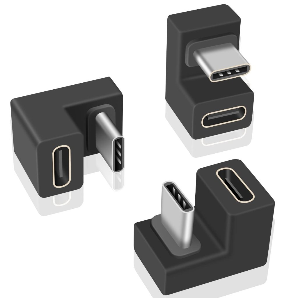
You can use two to make an USB ouroboros.
Damn, I have only one. But instead, I have a USB C -> A and an A -> C adapters: I make a snake that ate an elephant out of them.
It’s stupid, but now that you say that, I want them despite having no particular use for them.
The right angle ones are useful for the Steam deck.
I appreciate your generous provision of an excuse I can use.
Why not just buy an off-the-shelf USB-C cable? The great thing about USB-C is that it’s not proprietary – you don’t have to make a custom-built replacement for something like this.
thanks for all the replies. I might experiment withnless solder, fewer lanes and some shielding, but probably it makes more sense to use the premade silicone cable and use the extra effort to design a part to snuggly house that.
Way less solder. Avoids shorts. Clean up the flux!
Still, USB C is rather picky about signal quality. You don’t have the data cables twisted and shielded as they should, and length equivalence of data lines is probably only eyeballed.
I’d actually be surprised if it worked.